C++ Builder CEサウンドプログラミング
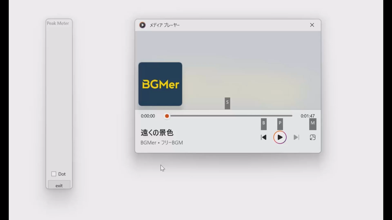
システム音を拾って、ピークメーターに似た表示を行うプログラムを作る。できあがりの感じの動画は、
使っている楽曲は、BGMerさん提供の”遠くの景色”です。メディアプレイヤーで再生している音声レベルに応じてバーを表示します。ま、これを作るには、色々なアプローチがあるとは思いますが、システムで再生されているレベルを捉えることがまず必要です。それは、
#include <mmdeviceapi.h>
#include <endpointvolume.h>

IMMDeviceEnumerator *pEnumerator = NULL;
IMMDevice *pDevice = NULL;
IAudioMeterInformation *pMeterInfo = NULL;


........

	HRESULT hr;
	CoInitialize(NULL);
	hr = CoCreateInstance(__uuidof(MMDeviceEnumerator),
						NULL, CLSCTX_INPROC_SERVER,
						__uuidof(IMMDeviceEnumerator),
						(void**)&pEnumerator);
	if ( FAILED(hr) ) {
		ShowMessage("CoCreateInstance failed");
		return;
	}
	hr = pEnumerator->GetDefaultAudioEndpoint(eRender, eConsole, &pDevice);
	if ( FAILED(hr) ) {
		ShowMessage("GetDefaultAudioEndpoint  failed");
		return;
	}

	hr = pDevice->Activate(__uuidof(IAudioMeterInformation),
						CLSCTX_ALL,NULL,(void**)&pMeterInfo);
	if ( FAILED(hr) ) {
		ShowMessage("device activate failed");
		return;
	}
		hr = pMeterInfo->GetMeteringChannelCount(&chcount);
	if( FAILED(hr)){
		ShowMessage("get ch count failed");
		return;

	}


	Timer1->Interval = TIMER_PERIOD;
	Timer1->Enabled = true;
等として、準備しておいて、実際の音の大きさを拾うのは、タイマードリブンなルーチンで、
void __fastcall TForm1::Timer1Timer(TObject *Sender)
{
	HRESULT hr;
	int numl,numh;
	char    obuf[80];

	hr = pMeterInfo->GetChannelsPeakValues(chcount,apeak);
	if( FAILED(hr)){
		ShowMessage("get ch values failed");
		Timer1->Enabled = false;
	}
	//ProgressBar1->Value = apeak[0]*100;
	//ProgressBar2->Value = apeak[1]*100;
	//now = GetTickCount();
	//updatebar1all(apeak[0]);
	//updatebar2all(apeak[1]);
	//aled->clear();
	numl = apeak[0]*NUMLEDS/2;
	numh = NUMLEDS-1-apeak[1]*NUMLEDS/2;
	for( int k = 0 ; k < NUMLEDS ; k++ ){
		if( k <= numl || k >= numh){
			if( k <= numl )
				leds[k] = tables[k];
			else
				leds[k] = tables[29-k];
		}
		else
			leds[k].setRGB(0,0,0);
	}
	if( numl == 0 )
		leds[0].setRGB(0,0,0);
	if( numh == NUMLEDS-1 )
		leds[NUMLEDS-1].setRGB(0,0,0);
	//	sprintf(obuf,"peak detected now:%g old:%g\n",apeak[0],lastl);
	//	OutputDebugString((LPCWSTR)obuf);
	/* peak and hold */
	if( apeak[0] < lastl ){
		//leds[(int)(lastl*NUMLEDS/2)].setRGB(30,0,0);
		unsigned char r,g,b;
		r = tables[(int)(lastl*NUMLEDS/2)].r;
		g = tables[(int)(lastl*NUMLEDS/2)].g;
		b = tables[(int)(lastl*NUMLEDS/2)].b;
		leds[(int)(lastl*NUMLEDS/2)].setRGB(3*r,0,0);
		lastl = apeak[0];
		lastl -= 0.12;
		//sprintf(obuf,"peak detected %g %g\n",apeak[0],lastl);
		//OutputDebugString((LPCWSTR)obuf);
	}
	else
		lastl = apeak[0];
	if( apeak[1] < lasth ){
		unsigned char r,g,b;
		r = tables[NUMLEDS-(int)(lasth*NUMLEDS/2)].r;
		g = tables[NUMLEDS-(int)(lasth*NUMLEDS/2)].g;
		b = tables[NUMLEDS-(int)(lasth*NUMLEDS/2)].b;
		leds[NUMLEDS-(int)(lasth*NUMLEDS/2)].setRGB(3*r,0,0);
		lasth = apeak[1];
		lasth -= 0.12;
	}
	else
		lasth = apeak[1];
	/* */
	aled->showleds();
	PaintBox1->Repaint();
	PaintBox2->Repaint();
}
//---------------------------------------------------------------------------
ここではTIMER_PERIOD=25で、25msということなので毎秒40サンプルという前提ですね。上のタイマールーチンでバレているように、前記事のws2812bなLEDに画面と同様なディスプレイを行います。LEDが使えれば。同期再生している状況の動画は、
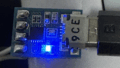
右側のフレームの上の方に映り込んでいるのは、USB経由での消費電流と出力電圧を計測し表示している装置で、

同様なものはまだ秋月電子から購入できるようです。上の動画では、最大の負荷電流は50ないし60mA程度ですからUSB2.0の定格内に収まっています。WS2812BなLEDは今回は円形に並べた24素子を使いました。従ってNUMLEDSは24に定義しています。cpu-zによると、
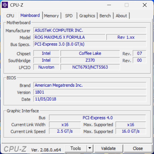
M/BはASUSのROG MAXIMUS X FORMULA Rev 1.xxなので、こちらのM/B側ではなくUSB2.0の許容電流の最大値は500mAまでと考えられます。まだ余裕がありますかね。
コメント